1

SR latches and T-flip-flops are trivial circuitry in Minecraft redstone, but it appears that there is little to be found for a circuit that combines both, allowing for both SR and T functionality.

I envision an SR-T latch to have set, reset, and toggle inputs respectively, but all connected to the same memory cell. This means that the output can be controlled by setting it, resetting it, and toggling it all at once. Just like an SR latch, pressing S or R when the cell is already in that state should do nothing.

All of my circuitry so far has been "unclean" implementations, either a bodged wiring to add a toggle to an SR latch, or bodged wiring to add SR inputs to a T-flip-flop. What is the best way to go about making such a latch?

See also: Same question for Bedrock Edition (originally one question; separated upon request from others)

3 Answers 3

1

Maybe there's a compact way to do exactly what you want in one circuit element, but you can also just use a regular RS-NOR latch and then a circuit element that inverts signals on request.
I tried out a bunch of complex ideas around this, until I realised that this comes down to a simple logic gate, with this logic table:

┌───┬───┬───┐
│IN1│IN2│OUT│
├───┼───┼───┤
│ 0 │ 0 │ 0 │
│ 0 │ 1 │ 1 │
│ 1 │ 0 │ 1 │
│ 1 │ 1 │ 0 │
└───┴───┴───┘

Therefore, what you want is an XOR gate. The Minecraft wiki has tutorials for those: https://minecraft.wiki/w/Mechanics/Redstone/Logic_circuit#XOR_gate (archive)


Just so this is a complete answer (and not considered a link-only answer), here's a screenshot of one of the alternative designs. Of course you'll realistically want to compare the different designs on the wiki and pick one that works best for your situation.

7
  • I'm not really following how a 2 lever input XOR works in place of a 3 button input RS+T. I guess would you hook up the S line on an RS-NOR to IN1, then a T output to IN2 here?
    – Unionhawk
    Commented May 18, 2020 at 20:04
  • The output of your RS-NOR latch is one input lever, the inversion button is the other lever. I don't know what you mean with "S" and "T". Commented May 18, 2020 at 21:10
  • In other words, such that the final black-box diagram looks like this: i.sstatic.net/2KuJP.png
    – Unionhawk
    Commented May 18, 2020 at 21:21
  • The top left box would be the RS-NOR latch and the bottom left box would not exist, it would just be a lever input. Commented May 18, 2020 at 22:10
  • Ooh, I like your concept, but unfortunately there is one unacceptable flaw: Based on your last comments with the RS-NOR being on the first lever and the toggle input on the 2nd, it works fine, except for the fact that when the toggle lever is ON, not only does it invert the output, it also inverts the RS-NOR's controls, i.e. the ON button will turn it OFF, and the OFF button will turn it ON. I need the toggle input to invert the output but NOT the controls.
    – One 2 Many
    Commented May 18, 2020 at 23:08
1

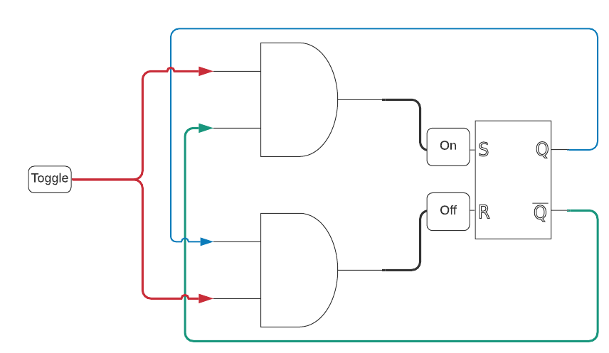
What you're looking for is still going to be based primarily around an RS latch, with a couple of AND gates to make the toggle line work properly. For this, the circuit diagram looks like this:

Circuit diagram consisting of an RS latch and a pair of AND gates

Breaking it down, you have an RS latch hooked up as normal. From there, you need the output and an inverted output to control two AND gates that control which input the Toggle is meant to control. That is, if the RS state is on, your toggle should control the off side of the RS latch.

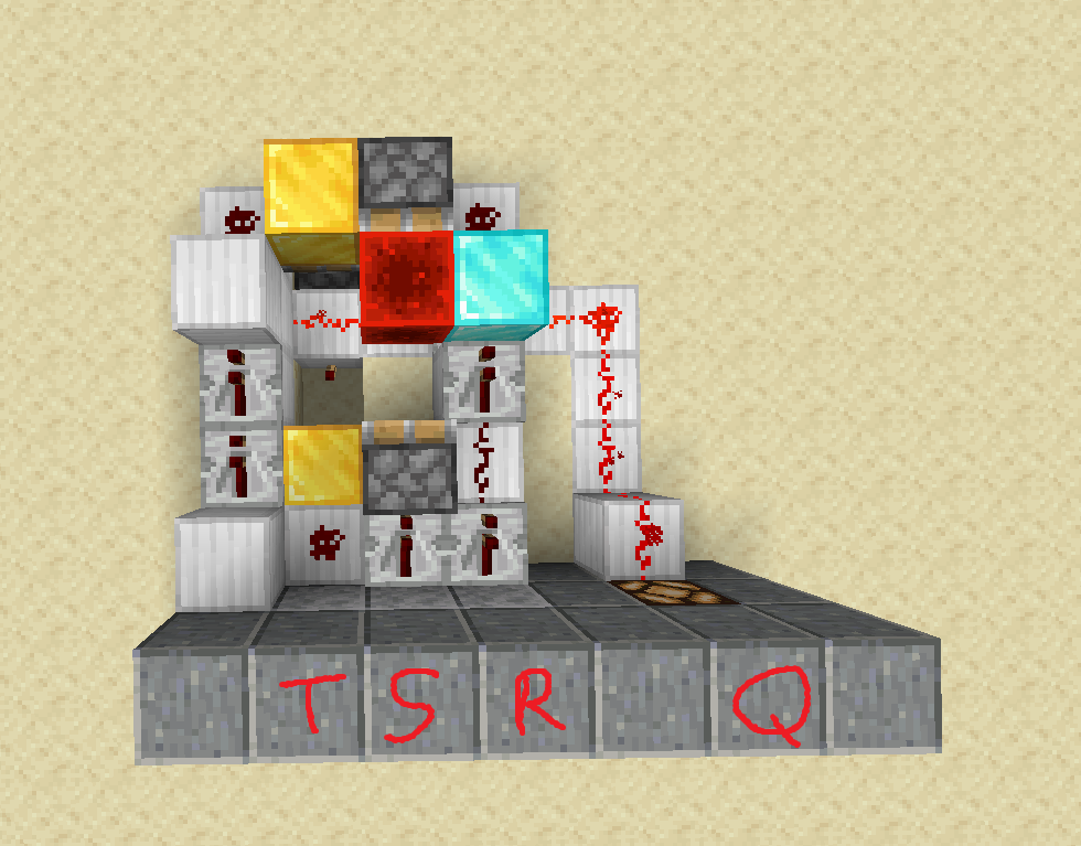
I'm sure this could be done more cleanly, but the circuit I came up with is this:

The above circuit implemented in Minecraft

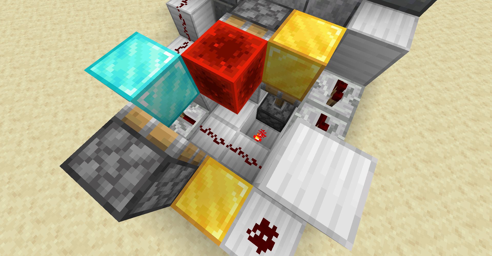
Note that in the above there are sticky pistons underneath the gold blocks which act as AND gates, and a redstone repeater underneath the diamond block to keep the signal from the repeater on the Reset line from being directly connected to the Output line. Here's a closer look at that portion of the circuit:

Closer look at the AND gates and the repeater in the Q line

2
  • @ExpertCoder14 I added a screenshot to zoom in on the AND gate pistons. As far as I'm aware, this should work in Bedrock Edition.
    – Unionhawk
    Commented May 19, 2020 at 15:55
  • @ExpertCoder14 Hmm, interesting. Having built it myself in Bedrock I see what the issue is now. The build doesn't utilize quasi-connectivity and gets away with it because Java edition. However, since it does contain diagonal power to pistons, it fails in Bedrock edition.
    – Unionhawk
    Commented May 19, 2020 at 20:39
0

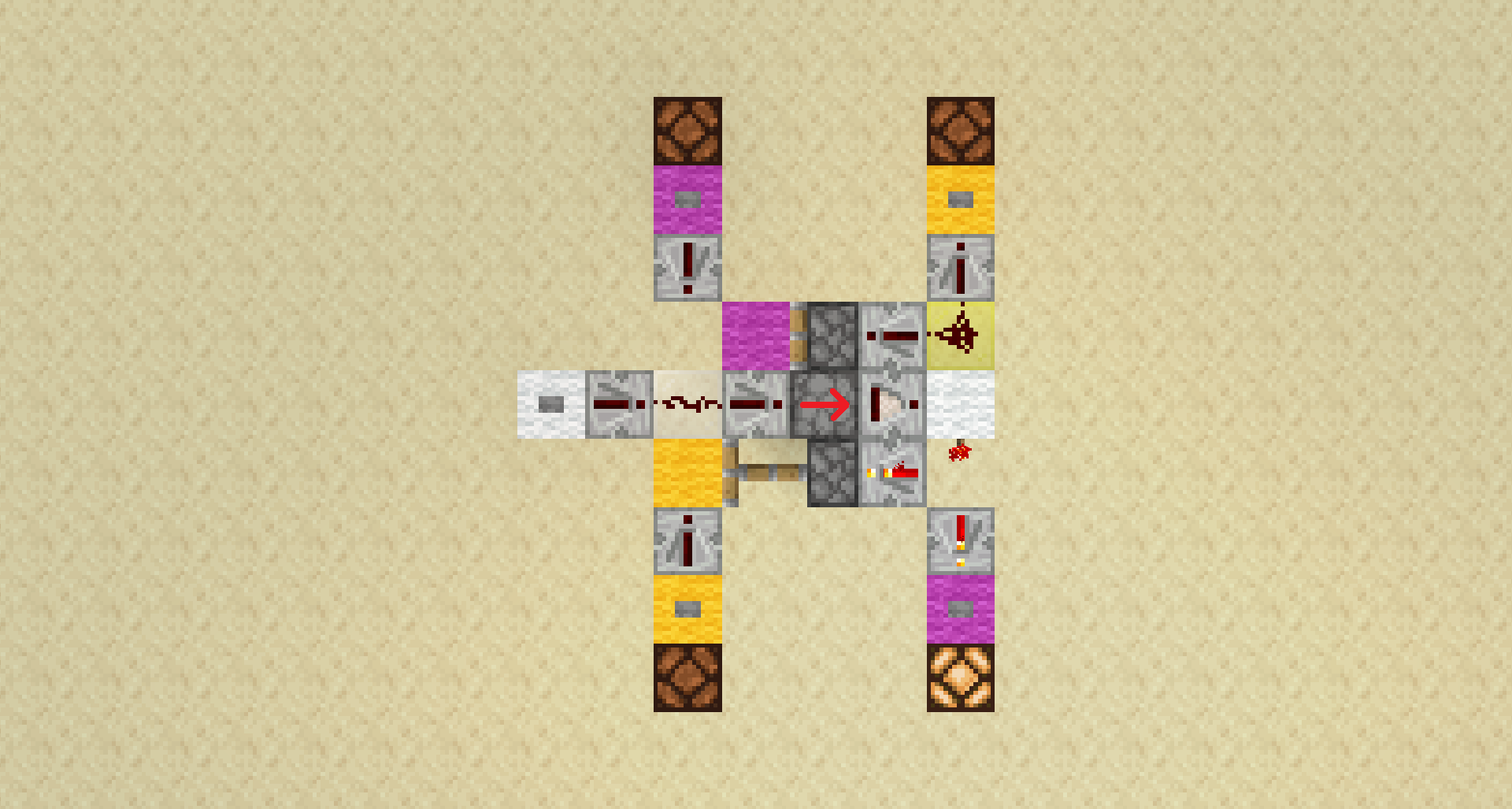
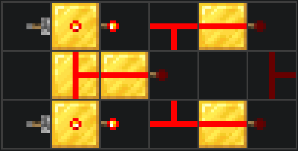
I have managed to create a compact design for this so-called “SRT latch:”


This circuit uses a T-flip-flop as its base. The T-flip-flop's output is used to activate pistons that complete a circuit from the corresponding S/R input to the toggle input. This effectively treats the S/R buttons as “conditional toggles.”

This circuit is compact, simple, and uses its space effectively with a symmetrical layout. At its bare minimum, the footprint of this circuit is 5×3×2, excluding the space taken by the inputs and outputs.

Upon further thought, it turns out that this circuit is, in essence, a JK flip flop, the only difference being that the toggle function is controlled by a separate input, rather than with both inputs being on at once. This could theoretically render this design as one of the most compact JK flip flop designs in Minecraft.

This circuit is likely to work on MCBE, but has not yet been tested. I will transcribe this answer to the other question if I can confirm its functionality.

Your Answer

By clicking “Post Your Answer”, you agree to our terms of service and acknowledge you have read our privacy policy.

Not the answer you're looking for? Browse other questions tagged or ask your own question.